How Trailer Electric Brake Magnets Work. A Complete Explanation.
Learn how electric brake magnets use electromagnetic force to activate your braking system, including how to inspect, test, and replace them for safe and reliable stopping performance.
Published: April 22, 2026 by Allred Trailer Service
If you tow a loaded trailer, your electric brakes are one of the most important safety systems on your rig. At the heart of every electric brake assembly is a small but critical component: the electromagnet. Understanding how that magnet works, what it contacts, and how it translates electrical current into stopping force will help you diagnose problems faster, maintain your brakes correctly, and know when it is time to replace parts.
This post covers the full picture, from the physics of the electromagnet to the drum's armature surface, amperage specs, wear inspection, and common failure modes. All technical data is drawn from Dexter axle service manuals 600-8K (light/medium duty) and 9-15K (heavy duty).
Need axle parts for your trailer?
https://brakes4trailers.com/allred
What Is a Trailer Electric Brake Magnet?
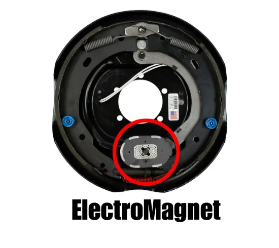
A trailer electric brake magnet is a high-capacity electromagnet mounted on a pivoting lever arm inside the brake assembly. It is not a permanent magnet. It only becomes magnetic when electrical current flows through its internal coil. When energized, it is attracted to the spinning inner surface of the brake drum, and that attraction is what sets the braking sequence in motion.
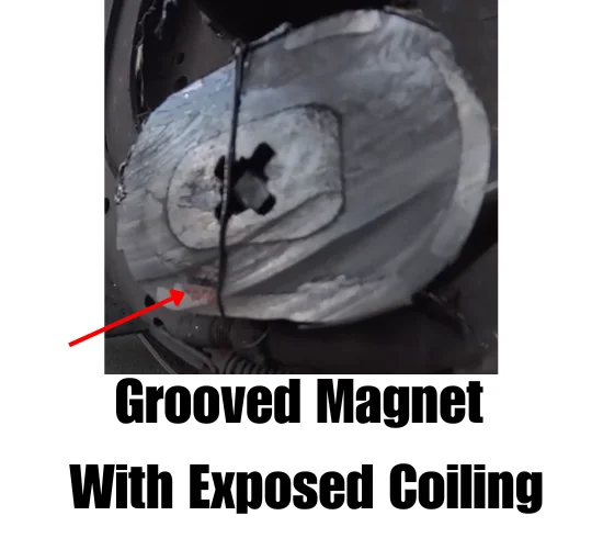
The magnet assembly consists of a wound coil embedded inside a friction-material facing. The friction material is what physically contacts the drum. Over time, that facing wears down just like a brake shoe, and the coil itself can be exposed if the wear goes too far.
How the Magnet Generates Braking Force
The sequence works like this:
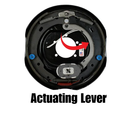
When the driver applies the brakes, the in-cab brake controller sends electrical current through the trailer wiring to the electromagnets in each brake assembly. The energized magnets are attracted to the rotating armature surface of the drum and are dragged in the direction the drum is spinning. This rotational drag pulls the magnet's actuating lever in the same direction the wheel is turning.
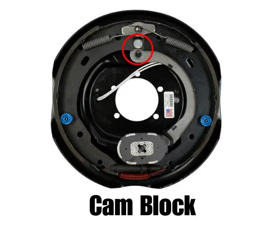
The lever is connected to an actuating cam block at the shoe end. As the lever pivots, the cam block pushes the primary shoe outward against the inside surface of the drum. The force generated by the primary shoe then acts through the adjuster mechanism to push the secondary shoe into contact with the drum as well.
Increasing the current to the magnet increases its grip on the armature surface. That stronger grip translates directly into greater pressure against the shoes and drum, producing more braking force. The controller governs how much current flows based on deceleration demand, which is why a properly adjusted controller is essential to smooth, proportional braking.
The Armature Surface: What the Magnet Actually Contacts
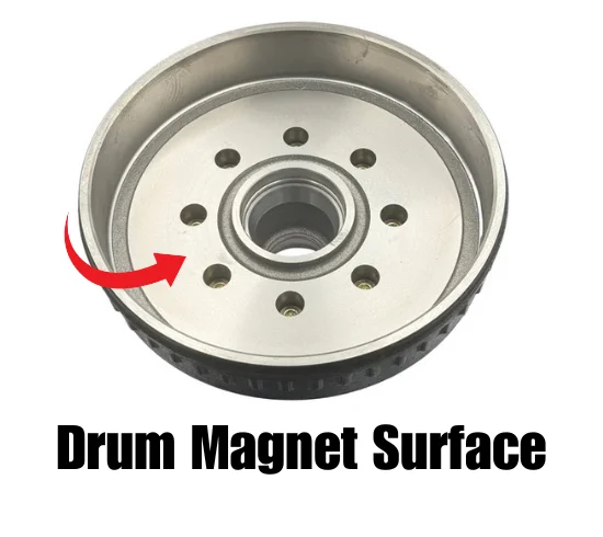
The magnet does not contact the brake shoe lining surface. It contacts a specific machined area on the inner face of the brake drum called the armature surface. This is a precision-machined ring on the inside of the drum that is separate from the shoe contact surface.
Because the magnet physically rides against the spinning armature surface, both components wear together. Dexter specifies that the armature surface should be refaced whenever magnets are replaced, and that magnets should be replaced whenever the armature surface is refaced. Skipping one side of that pairing leads to poor contact, reduced braking force, and accelerated wear on whichever new component is installed.
If the armature surface is scored or worn unevenly, it should be refaced to a 120 micro inch finish, removing no more than 0.030" of material. When drum turning or armature refacing is performed, it is critical to protect the wheel bearing bores from metallic chips. Contamination in the bearing cavities will cause premature bearing failure.
Magnet Resistance and Amperage Specs
A properly functioning Dexter brake magnet should measure 3.2 ohms when checked with an ohmmeter. This is the standard test used after prolonged storage or whenever a magnet's condition is in question. A reading that deviates significantly from 3.2 ohms indicates a shorted or open coil, and the magnet must be replaced.
Current draw at full voltage should be approximately 3.0 amps per magnet. System amperage scales with the number of brakes:
| Brake Size | Amps/Magnet | 2 Brakes | 4 Brakes | 6 Brakes |
|---|---|---|---|---|
| 12-1/4" x 3-3/8" (4", 5") | 3.0 | 6.0 | 12.0 | 18.0 |
Source: Dexter 9-15K Service Manual
Abnormally high system amperage points to a shorted circuit, which can be caused by shorted magnet coils, defective controllers, or bare wires contacting a grounded surface. Finding the source means isolating one section at a time. If amperage drops to zero when the trailer is unplugged, the short is in the trailer. If high amperage remains with all magnets disconnected, the short is in the trailer wiring itself.
Abnormally low amperage or no amperage at all is the more common problem. Typical causes include poor electrical connections, open circuits, undersized wire, broken wires, blown fuses, or a failing controller. Note that Dexter does not recommend fusing individual brake circuits.
Voltage and the Role of the Controller
System voltage is measured directly at the magnet lead wires. With the tow vehicle engine running, voltage should start at zero and rise gradually to approximately 12 volts as the controller is actuated. The threshold voltage, which is the voltage applied when the controller first activates, should be kept low to avoid grabby, harsh braking. A threshold voltage above 2 volts is a common cause of brake harshness.
All electrical troubleshooting should begin at the controller. The Dexter manuals note that most complaints about brake harshness or malfunction trace back to an improperly adjusted or non-functioning controller. The controller output wire (typically the BLUE wire) is the best location to measure system amperage with an ammeter in series.
Voltage drop due to loose or corroded connections is a frequent real-world problem. Every connection point in the brake wiring should be sealed to prevent corrosion. Corrosion increases resistance, which reduces the voltage that actually reaches the magnets, resulting in weak or inconsistent braking.
Minimum recommended hookup wire sizes per Dexter:
| Number of Brakes | Hitch-to-Axle Distance | Minimum Wire Size (Copper) |
|---|---|---|
| 2 | Any | 12 AWG |
| 4 | Under 30 ft | 12 AWG |
| 4 | 30-50 ft | 10 AWG |
| 6 | Under 30 ft | 10 AWG |
| 6 | 30-50 ft | 8 AWG |
Source: Dexter 600-8K and 9-15K Service Manuals
Undersized wire is a silent killer of brake performance. It limits current flow and causes the magnets to operate below their rated force output.
Magnet Wear Inspection
Magnets should be inspected at every brake service. The correct method is to lay a straightedge across the face of the magnet. A magnet in good condition should be flat. If gaps appear between the straightedge and the magnet face, that indicates uneven or abnormal wear and the magnet must be replaced.
Even if wear appears normal by the straightedge test, replace the magnet immediately if any portion of the coil winding is visible through the friction material facing. An exposed coil means the protective friction layer is gone and the coil itself will contact the drum, leading to rapid failure and potential electrical faults.
Magnets must always be replaced in pairs, meaning both magnets on the same axle. Replacing only one side creates an imbalance in braking force between the left and right wheels, which can cause trailer sway or uneven stopping.
Replacement Magnet Part Numbers (Dexter)
The following Dexter replacement magnet kits cover common light and medium duty brake sizes. One magnet per kit.
| Brake Size | Magnet Kit Number | Wire Color |
|---|---|---|
| 7" x 1-1/4" | K71-057-00 | White |
| 10" x 1-1/2" | K71-104-00 | Green |
| 10" x 2-1/4" | K71-104-00 | Green |
| 10" x 2-1/4" (4.4K) | K71-125-00 | Black |
| 12" x 2" | K71-105-00 | White |
| 12" x 2" (7K) | K71-125-00 | Black |
| 12-1/4" x 2-1/2" (7.2K) | K71-378-00 | Red/Black |
| 12-1/4" x 3-3/8" | K71-378-00 | Red/Black |
Source: Dexter 600-8K Service Manual
Heavy duty magnets manufactured after June 2017 use kit number K71-378-00 with red/black wiring across the 12-1/4" brake sizes for 9K through 15K axles.
Burnishing New Magnets
When new magnets are installed, they need to seat against the armature surface before delivering full braking performance. This break-in process is called burnishing. Dexter recommends applying the brakes 20 to 30 times with approximately a 20 mph decrease in speed (for example, 40 mph down to 20 mph) before making any controller adjustments. Allow time for the brakes to cool between applications.
For a detailed walkthrough of the burnishing procedure, see our guide: [How to Properly Burnish Your Trailer Brakes](https://allredtrailerservice.com/blog/how-to-properly-burnish-your-trailer-brakes).
Key Maintenance Rules for Trailer Brake Magnets
- Inspect magnets at every annual service, or more frequently under heavy use
- Use a straightedge to check for uneven wear across the magnet face
- Replace immediately if any coil winding is visible through the friction facing
- Replace magnets in pairs, both sides of the same axle
- Reface the armature surface any time magnets are replaced, and vice versa
- Check resistance with an ohmmeter; magnets should read 3.2 ohms
- Never get grease or oil on the magnet face or brake linings
- Seal all wiring connections to prevent corrosion and voltage drop
- Use the correct wire gauge for the number of brakes and trailer length
Frequently Asked Questions
How do I know if my trailer brake magnet is bad?
The most reliable field test is an ohmmeter check. A healthy Dexter magnet reads 3.2 ohms. A reading of zero indicates a shorted coil. An open circuit reading (no continuity) means the coil is broken. Visually, uneven wear shown by the straightedge test or a visible coil through the friction facing are clear replacement indicators.
Can I replace just one trailer brake magnet?
Dexter specifies that magnets must be replaced in pairs, meaning both magnets on the same axle. Replacing only one creates a braking imbalance that can cause trailer sway.
What causes trailer brake magnets to wear unevenly?
Uneven armature surfaces, misaligned magnet arms, contamination from grease or oil, and running brakes that have never been properly burnished are the most common causes. If the armature surface is grooved or out of true, the magnet face will wear to match that surface rather than remaining flat.
Does the armature surface need to be machined when I replace magnets?
Yes. Per Dexter, the armature surface should be refaced whenever magnets are replaced, and magnets should be replaced whenever the armature surface is refaced. This ensures proper contact between both surfaces and even wear going forward.
Why are my trailer brakes grabby or harsh?
Harsh braking is frequently caused by a threshold voltage above 2 volts on the controller, an improperly adjusted controller gain setting, or brakes that have not been properly burnished. Check controller adjustment first before assuming the magnets are at fault.
Need axle parts for your trailer?
https://brakes4trailers.com/allred
Need Help with Your Trailer Brakes?
Allred Trailer Service serves Northern California with expert trailer brake inspection, magnet replacement, drum machining, and full brake service. If your trailer is pulling to one side, braking unevenly, or you just need a thorough inspection before your next trip, give us a call.
Phone: (916) 251-9731
Website: [allredtrailerservice.com](https://allredtrailerservice.com)
Frequently Asked Questions
What resistance should a trailer brake magnet measure?
A properly functioning Dexter brake magnet should measure 3.2 ohms when tested with an ohmmeter. A reading significantly higher or lower indicates a shorted or open coil — the magnet must be replaced. This test is the standard bench check used after prolonged storage or any time magnet condition is in question.
How many amps does a trailer brake magnet draw?
At full voltage (12V), each standard brake magnet draws approximately 3.0 amps. A tandem axle trailer with 4 brakes draws approximately 12 amps total. Abnormally high system amperage points to a short circuit. Zero amperage points to an open circuit, poor connection, or failed controller output.
Can I replace just one trailer brake magnet?
No. Magnets must be replaced in pairs — both sides of the same axle at the same time. Mismatched magnets produce uneven braking force and can cause the trailer to pull to one side under hard braking.
Why do my new trailer brake magnets wear out quickly?
Rapid magnet wear almost always comes from a grooved armature surface on the drum. The magnet and armature surface wear together. Installing a new magnet against a scored drum will wear new grooves into it within a few thousand miles. Dexter specifies that the armature surface must be refaced to a 120 micro inch finish any time magnets are replaced — and magnets must be replaced any time the armature surface is refaced.
What is the armature surface on a brake drum?
The armature surface is a precision-machined ring on the inner face of the brake drum that the electromagnet physically contacts during braking. It is a separate wear surface from the inner drum surface where the brake shoes contact. Both surfaces must be inspected whenever the brake assembly is serviced.